Adding a PC compatible AT keyboard to a zx-spectrum
Background
Welcome to yet another yet another Sinclair Spectrum keyboard
interface !!
It all started when I came across an old Timer 2068... This resulted
in digging out an old 8 bit ZX-Spectrum and really really wanting
to play Manic Miner. The only problem was the membrane keyboard was
pretty much toasted.. but I did have lots of AT keyboards about the
place.
Time for some kind of interface !!!So what exactly is a zx-spectrum ? Well here's almost everything you
could want to know about this old 8 bit system from the 80's can be found
here World
of Spectrum and also here Planet
Sinclair.
Plus a BBC news story about the beastie How
the Spectrum began a revolution.
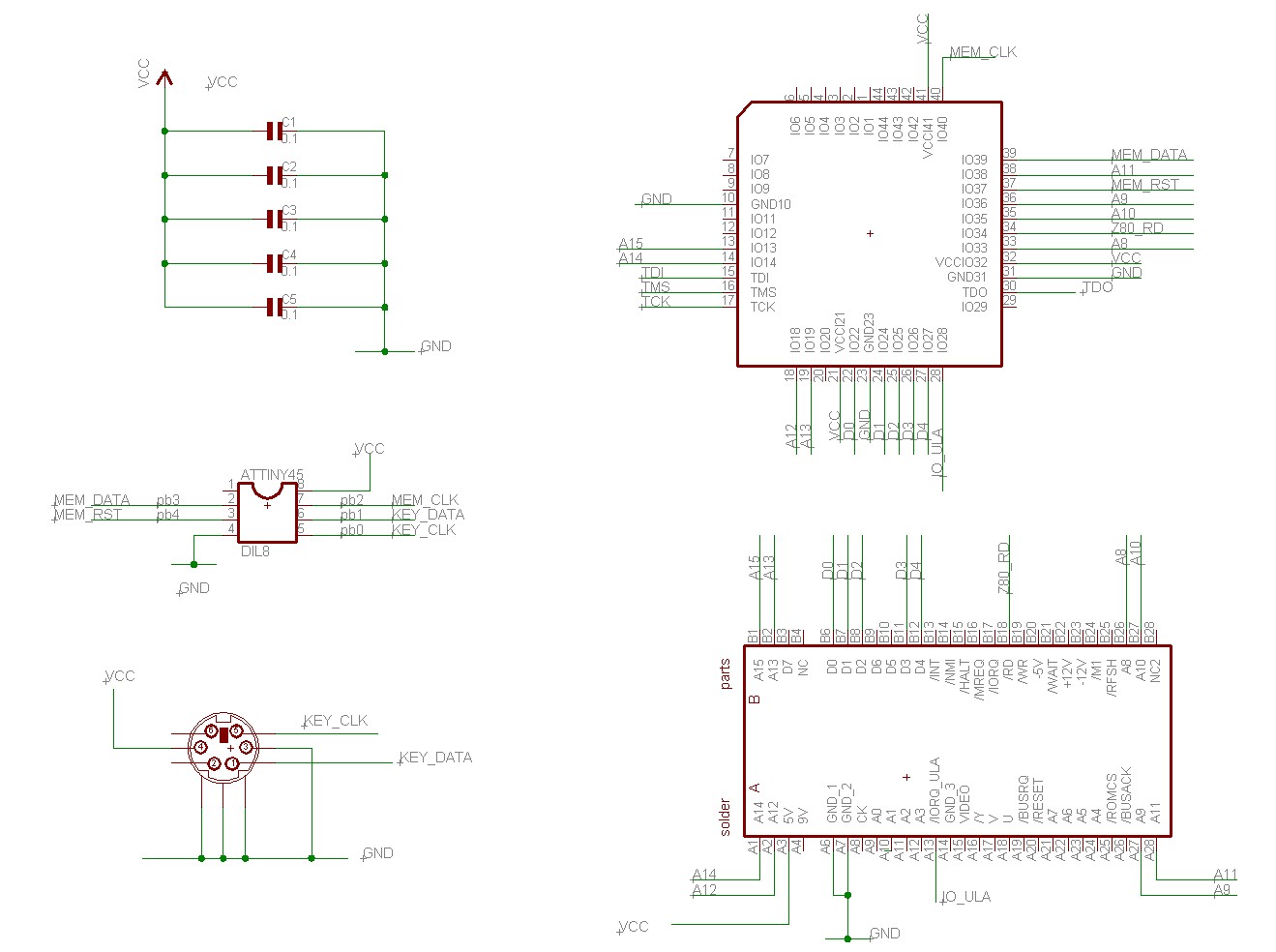
Theory
For anyone unfamiliar with the Spectrum the keyboard rows were read by
a z80 'in' op-code with one or more of the high address lines, A8 to A15,
being pulled low and the 5 column bits, D0-D4, being read from the
Sinclair ULA. The pressed key connected, via a diode, the ULA's keyboard
input bit, which was pulled high by a 10k resistor, to the low address
line and so forcing the input low. A very cheap, cheerful and
effective way of implementing a 40 key keyboard, 8 address lines x 5
bits = 40 keys.
So to emulate how the original works, it's just a case of reading in an AT
keycode, turning it into a 5 bit 'row value' and putting it on the
spectrum databus when a read of the keyboard is made for the row of the
corresponding high-address bit. Simple eh ?
|
|
|
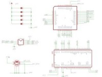
The Schematics
 |
 |
| Click for Schematics |
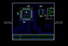
Click for PCB |
|
Download the project files
|
|
|
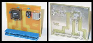
Design
The design has only two major components, an Amtel AVR ATtiny45 micro-controller (MCU)
and a XC9572 Xilinx complex programmable logic device (CPLD).
The Atmel micro-controller initializes and talks to the keyboard. The
keyboard is put into the mode "scan code set 3", which is a
simplified key mode where no extended codes are used which makes life easier.
Also the key auto-repeat is disabled. Auto-repeat
is handled by the spectrum so no need to use it on the keyboard end. The
controller program translates the 127 possible AT key codes into spectrum keyboard column
bits using a look-up table to map one to the other. See the AVR source
code for details.
Finally the micro-controller writes serially the state of all 40 keyboard
keys to the Xilinx programmable logic. The CPLD which acts like a 40
bit memory device storing the key
states of up or down and passing these to the spectrum when requested.
The most important thing the CPLD does, apart from storing the key
information, is handling I/O reads from spectrum ! When the spectrum reads
the keyboard using a z80 'IN' opcode the CPLD detects the IORGE with the
Z80 /RD line going low, which is the signal for a keyboard read, and
places onto D4 to D0 the state of the 'key bits' array. The bits are
controlled by the A8 to A15 address lines. A8 to A15 enables a particular
keyboard row and each of the D4 to D0 bits corresponds to a keyboard
column. As the ULA is effectively 'isolated' from the specturm databus,
the CPLD has effective priority, so it's data is read by the spectrum and
there's no contention with the ULA.
|
|
The Advantage of this design
Why's this design different from others ? Well.. on the original Spectrum you could read more than one row of keys at a
time by having more than one address line being low during a keyboard read. The big
advantage of this CPLD approach is that it can simulate this behavior. So if both
address line A8 and A10 are low, the CPLD will output the up/down key
status of BOTH those rows onto the databus, just like you'd see happening
with a real Spectrum.
|
|
Technical Notes on the Program & CPLD
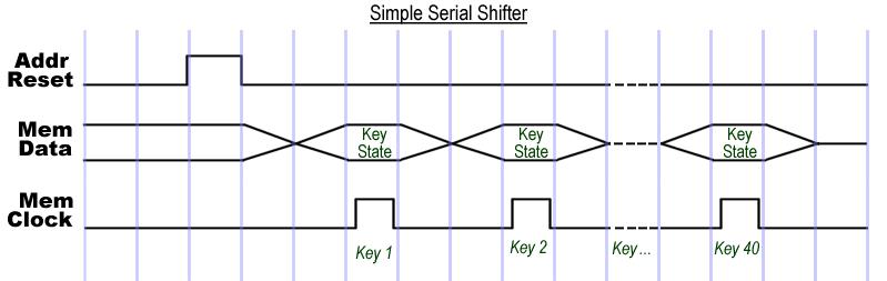
The serial shifter for the MCU to the CPLD is very simple, the MCU pulls
the 'mem reset' line high, then low to set the CPLD's internal address
counter to zero. Next it puts each bit representing the key state
onto the CPLD's 'mem-data' line and pulls the 'mem clk' clock input high,
at which point the CPLD stores that key state in it's internal 40 bit
memory. The MCU pulls the clock low and gets the next bit ready to send.
At this falling edge of the clock signal, the CPLD updates its internal
address counter to point to the next bit location in the 40 bit 'key bits'
memory array. After all bits have been written out the MCU pulls 'mem
reset' high causing the CPLD's internal memory address counter to be reset
back to zero. See the diagram for
details,
The micro-controller AT keyboard conversion table allows for multiple
spectrum keys in two different rows to be marked as 'pressed'
simultaneously. It can also set all the keys in one row as 'pressed' at
the same time too. This is really useful for the AT key 'delete', which is
translated to the spectrum codes for 'shift' and '0'. Also the arrow keys
are decoded to the spectrum 'shift' + direction keys.
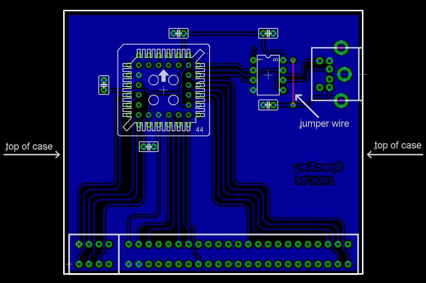
The pinning of the CPLD was made with reference to make the board layout
as easy as possible and ideally fit on a single sided PCB. In the end only
one jumper was required. So that pretty much met the design goals.
|
Versions + Enhancement
There's room for enhancement, the keyboard initialization code is a bit
quick-n-dirty, some better error handling could be added there.
The code and schematics are all free and open to modification, hacking,
enhancing, chewing or suchlike.
|
|
Schematics & PCB
Full schematics plus the prototype PCB designed in Cadsoft's Eagle
v4.1.
Software - Microcontroller + CPLD
The micro-controller program was written in AVR assembler, source
code for AVR studio 4.1 is provided.
The CPLD code was written in VHDL using Xilinx webpack ISE 8.2, the source
and project files are provided.
|
| |
| |
|
|