These modifications should be undertaken only if you have the relevant skills. I
cannot be held responsible for boards damaged while attempting this upgrade.
YOU PERFORM THIS MODIFICATION AT YOUR OWN RISK !!!
One thing that is sadly missing from Frogger is the ability to enter your
initials when you get a high score, so with this in mind I wrote some new
routines to allow you to enter your initials when you get a high score. To make
this really worth while I also added the ability for the game to save the
high-score table to non-volitile SRAM.
Should you just want to use the updated ROMs you DO NOT need to add the extra
RAM, they will run fine without the RAM except the scores will reset when power
is lost.
This is an update of the original high-score save for frogger that I made just
over a year ago. If there is much interest I could see about using a serial
EEPROM instead of a non-volatile SRAM.
The details below outline the modifications that are required to
make Frogger save it's high scores, the project is in two parts.
How this all works ?
The board mod adds an additional 2k x 8 SRAM appearing in the low memory area
$7000-$7FFF.
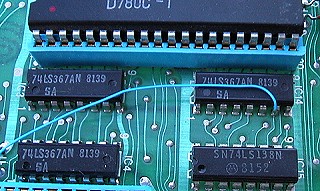
SRAM control inputs /OE ( output enable ) & /CE ( chip enable ) are tied to
IC18 ( 74LS138 ) pin 7, this is the low memory address decoder. SRAM /WE (
write enable ) is tied to the buffered z80 /WR line IC14
(74LS367 )pin 7.
When memory in the region of $7000-7fff is accessed, by a read or a write
operation by the z80, then "output 7" of IC18 goes low, pulling
the SRAM /CE ( chip enable ) and /OE ( output enable )
low.
If the z80 is performing a read operation the /WE line remains high and output
from the SRAM appears on the databus, if the /WE line goes LOW, the z80 is
performing a write operation signalled by the z80 /WR line going low, and the
buffer output at IC14 pin 7 also going low the, SRAM goes into write mode and
data is read from the databus, into the SRAM.
The schematics are here. Frogger High Score Save -
RAM schematics
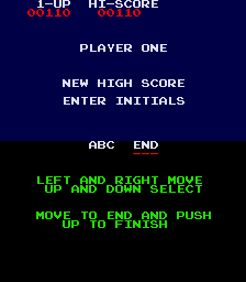
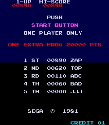
Here are two screen shots of what gets added to the game
Initials now recorded on High Score table.
High-score table displayed when game is coined and ready to play
High-score table saved to battery backed RAM
Reset of high-score table if 1P start, 2P start and player one UP are held down during machine power on.
24 pin IC socket
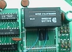
Dallas 1220 battery backed SRAM
4 inches of jumper wire
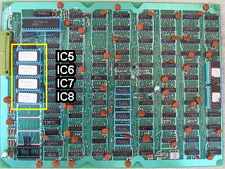
Four 2732 ROMs with new program images
Small piece of insulation tape
The Frogger board comes in two parts, a smaller upper board with the edge connector and a large lower board, all modification are performed to the lower board.
Note: this modification is for the Sega/Gremlin boardset with the Konami style pinout, not the Sega Galaxian's style boardset
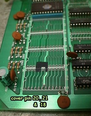
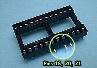
Step 1 Using some electrical insulating tape, cut a small piece big enough to completely cover the holes for pins 18, 20 and 21 at location IC12. See the picture. This is where the socket for the RAM will be located. Note the tape is about 1/4inch ( 6mm) in length, this is to cover the bent pins from the socket in the next stage. Note: The through holes on the board may all be filled with solder, if this is the case you will need to remove the solder from these holes so you can fit a socket in place. |
 |
Step
2 Using a 24 pin IC socket bend pins 18, 20 and 21 so they sick out horizontally at the side. These pin are /WE ( write enable ) and /CE (chip enable ) for the RAM we'll be using.
|
||||||
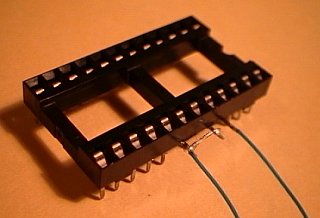
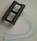
Step 3 pins 18 & 20 must now be joined together, and a jumper wire soldered onto them Second short jumper need to be soldered onto pin 21. These leads need to be approximately 2 inch ( 50mm) in length.
|
Soldered Leads |
Socket & leads
|
||||||
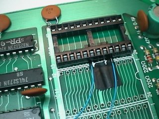
Step 4 Place the socket, with the soldered leads, into the board at location IC12. Note how the two angled pins are insulated from the board by the electrical tape below. Ensure all pins, apart from 18, 20 & 21 are though the holes and solder the socket in place. |
|
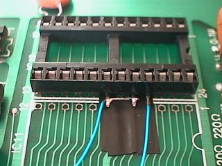 |
||||||
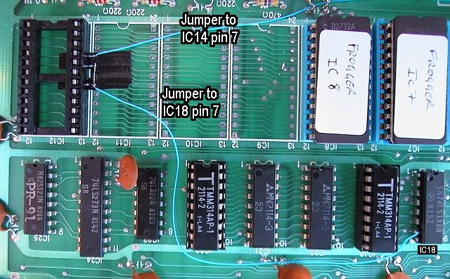
Step 5 Jumper wires now need to be soldered into place. Jumper connected to pins 18 & 20 should be soldered onto IC18 pin 7. Jumper connected to pin 21 should be soldered onto IC14 pin 7. |
|
|||||||
|
||||||||
|
That should be it ! Check your work, re-assemble the board and power the game up
Mail comments/Suggestions to |
||||||||
Frogger board modifications JROK-1999/2001